Part
Battery-box-style metal enclosure
The sample demonstrates welding around a metal box/enclosure form related to battery box and battery tray manufacturing.
A practical workshop case showing robot-mounted laser welding on a battery-box-style metal enclosure, with sound-enabled English-captioned videos, setup notes, wire-feeding context, and weld detail review.
The sample demonstrates welding around a metal box/enclosure form related to battery box and battery tray manufacturing.
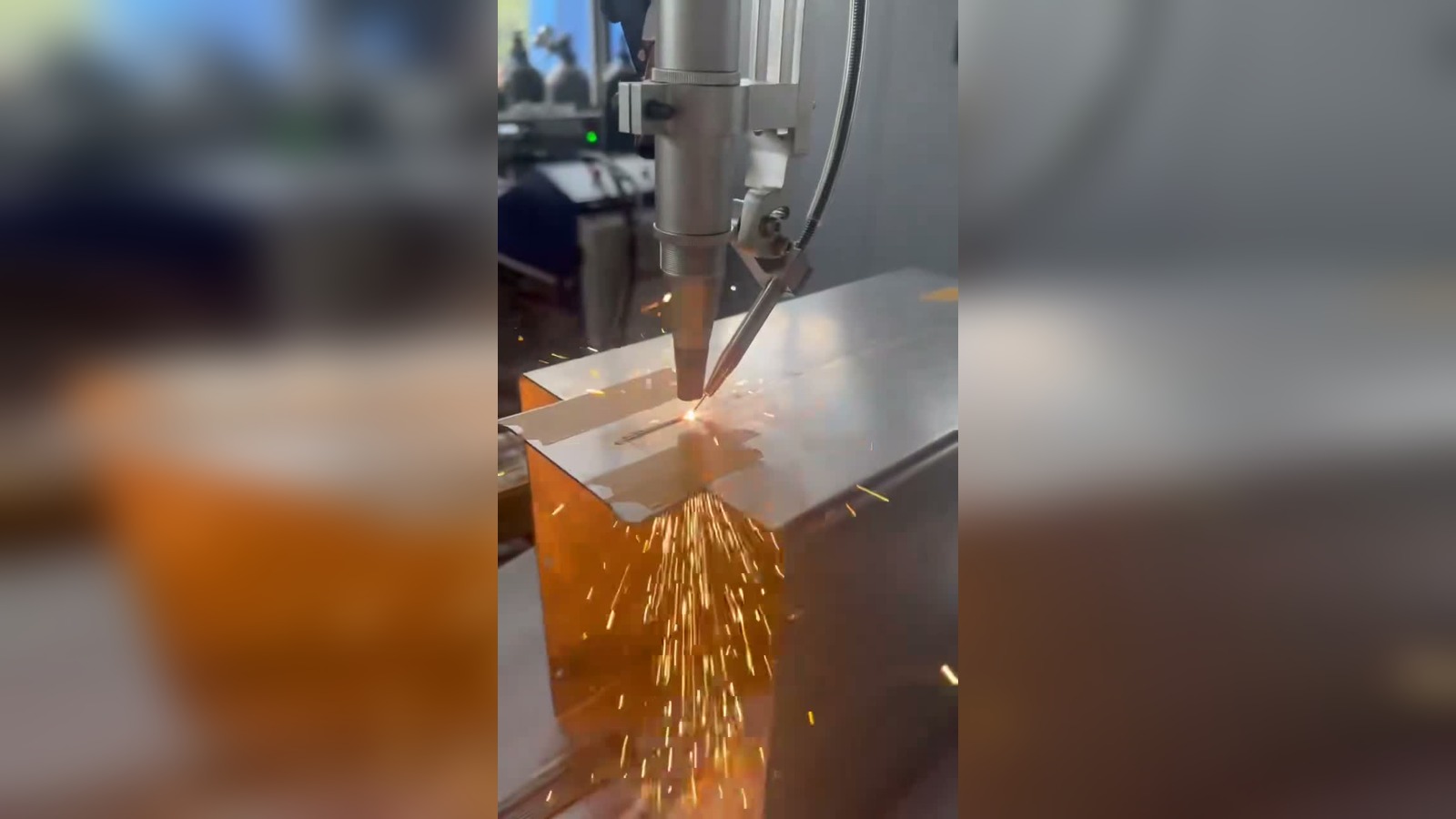
The robot carries the laser welding head along the seam path after workpiece positioning and process setup.
The visit also clarified how saved welding parameters are called and why push-pull wire feeding matters for irregular paths.
The edited overview keeps useful site audio and adds burned-in English technical captions so overseas customers can understand the process without relying on the raw Chinese conversation.
Battery boxes, battery trays, energy storage enclosures, and similar sheet-metal structures often include long seams, corners, and fitted edges. Weld consistency depends on workpiece fit-up, fixture repeatability, seam accessibility, laser process window, wire feeding stability, and shielding gas coverage.
The source recordings include technical notes about a stainless-steel sample, filler-wire welding, saved process settings, and communication options. Final production values should always be confirmed against the customer drawing, material certificate, fixture, and acceptance test.
These public videos include workshop sound and concise English captions. They are intended for technical review, not as final customer acceptance evidence.
Close-up footage shows the welding head tracking the seam with visible sparks, welding sound, and a narrow weld area.
The robot-mounted laser welding head approaches and follows the fixture/workpiece area for path verification and motion review.
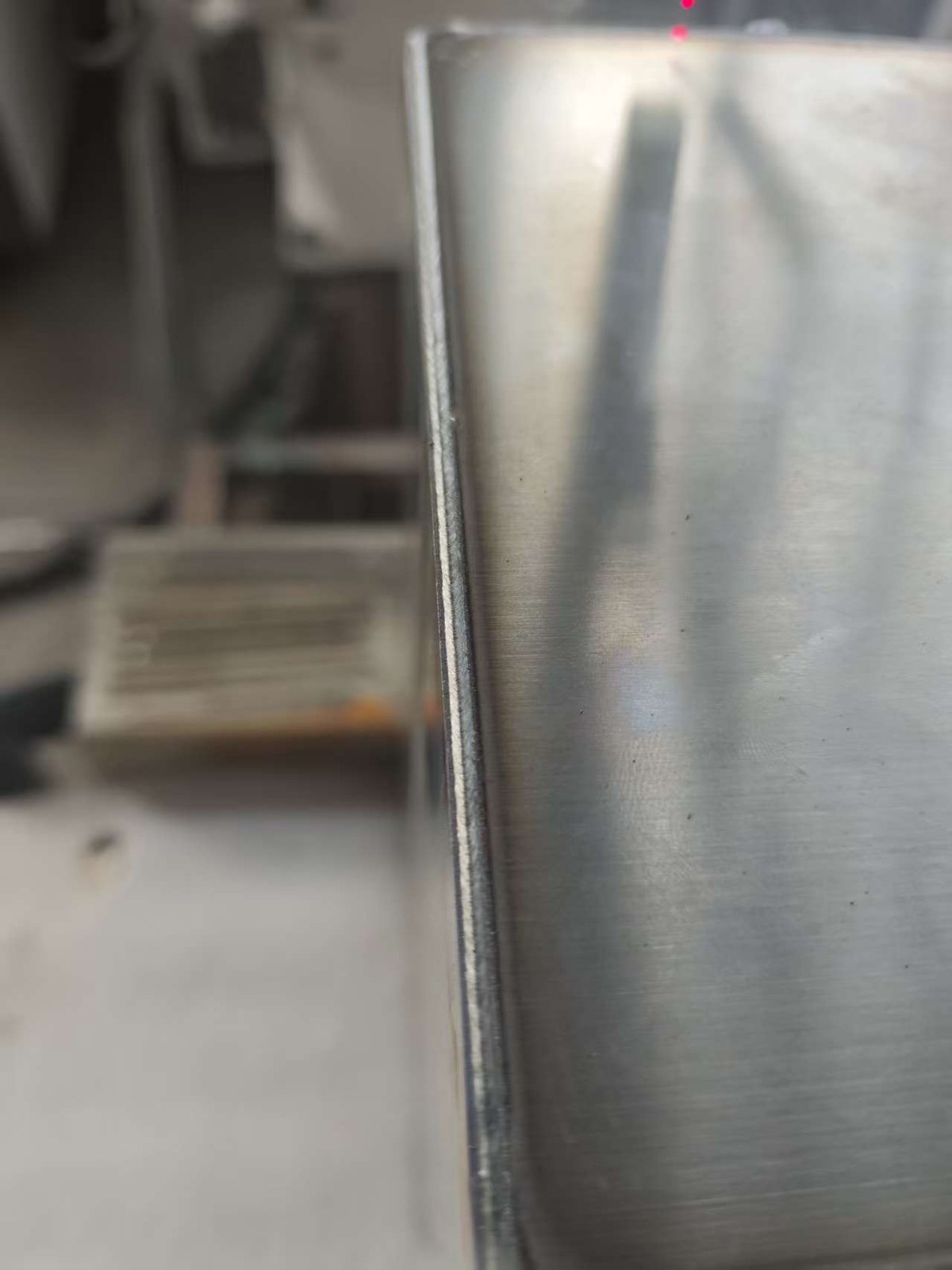
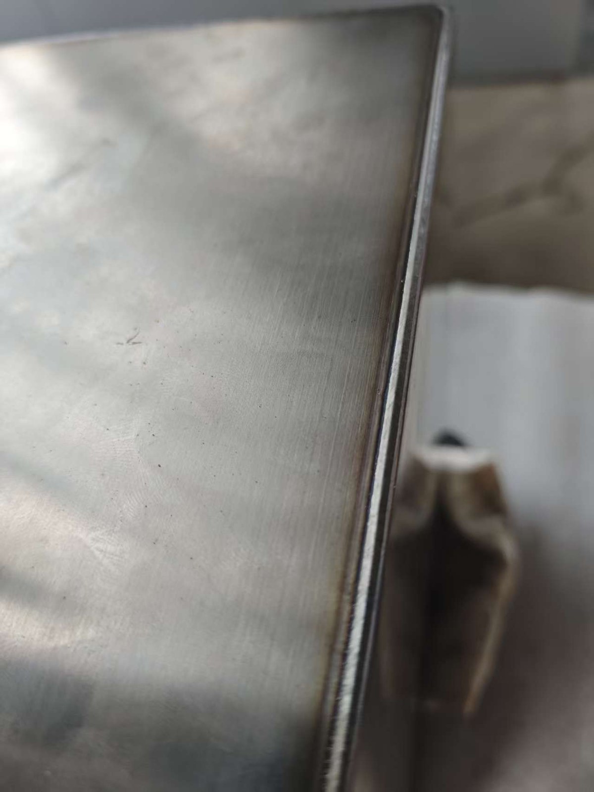
Finished sample footage and close-up still images support visual review before formal inspection.
A pre-built welding parameter package should be understood as saved and tested process settings that can be called quickly during commissioning. The robot path still needs to be taught or programmed according to the actual weld seam; the package does not automatically generate the path.
For repeat products or multiple seam types, saved parameter sets can reduce repeated trial-and-error, make operator training more consistent, and shorten the time needed to return to a proven process window.
Integration can be planned through the communication method that fits the robot and controller architecture, such as EtherCAT, IO, Modbus TCP, or Profinet.
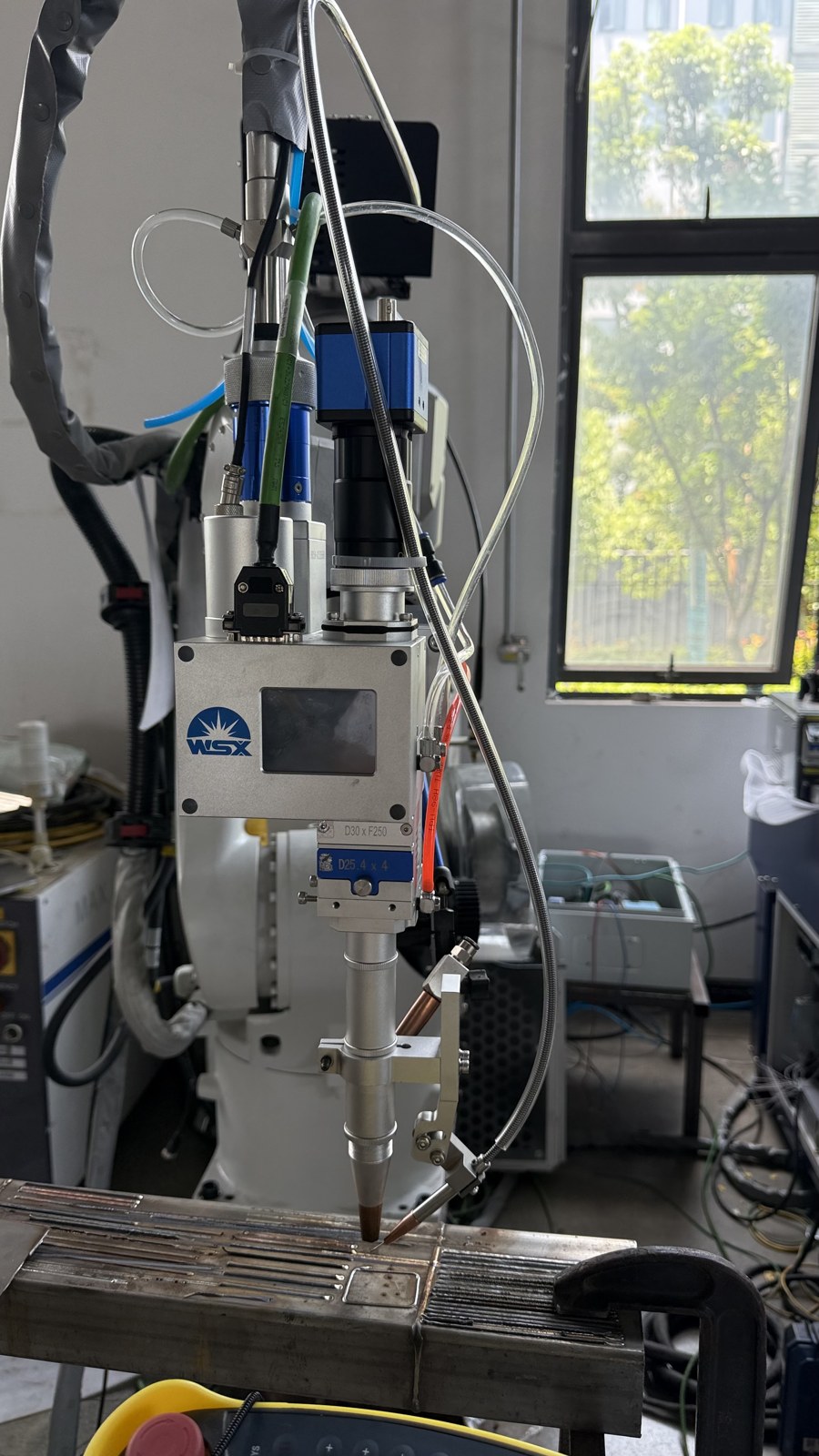
Standard push wire feeding can be cost-effective for simpler straight seams. For S-shaped, wave-like, or irregular paths, push-pull wire feeding can improve wire delivery stability because wire movement is controlled closer to the welding head.
When a customer is evaluating nonlinear filler-wire laser welding, a separate push-pull demonstration using a similar path is recommended.
This video shows how the welding workflow and parameter page are reviewed on the teach pendant. It helps explain that a parameter package is a saved process recipe for faster setup, while the robot path still needs to be taught or programmed for the actual seam.
This supplemental video explains the push-pull wire feeder hardware and the torch-side feeding path. The actual box sample should still be treated separately from a true S-shaped proof test, so a dedicated S-curve or wave-path demo is recommended if the customer needs direct evidence.
SkyFire can help evaluate whether robotic laser welding, filler-wire laser welding, or push-pull wire feeding is suitable for your battery box, enclosure, tray, or sheet-metal structure.